Introduce the concept of building details drawing and explain their importance in ensuring construction accuracy. You can also mention how they link design intent with on-site execution.
What Is a Building Details Drawing?
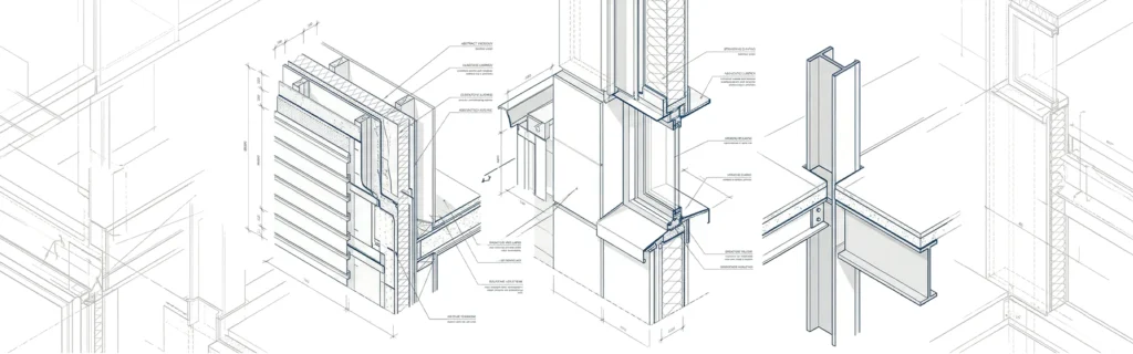
- A building details drawing is a technical drawing that focuses on a specific part of a building, shown at a larger scale than general plans.
- It explains exactly how components such as walls, slabs, windows, doors, roofs, or staircases are built and connected.
- The goal is to translate the architect’s and engineer’s design intent into clear, buildable information for contractors and site teams.
- Unlike floor plans and elevations, which show the overall layout, detail drawings zoom into junctions and layer build-ups.
- These drawings often show materials, thicknesses, insulation, waterproofing, finishes, and fixing methods in one clear view.
- A building details drawing usually includes references back to plans and sections using callouts and section marks so the drawing is easy to locate in the full set.
Why Building Detail Drawings Are Important
- Detail drawings reduce ambiguity on site and help prevent costly mistakes and rework.
- They improve coordination between architectural, structural, and MEP disciplines at critical junctions.
- Clear details support better cost estimation because quantities, materials, and methods are well defined.
- Good detailing improves the durability, safety, and performance of the building over its life cycle.
- Building details drawings also help contractors plan construction sequences and choose appropriate tools and methods.
- In many projects, authorities and clients review key details to verify compliance with building codes and specifications.
💡 Get BIM documentation service with accurate building details | [Contact AMC Engineer →Contact Us]
Main Types of Building Details Drawing
Architectural detail drawings
- Wall sections showing structural layers, insulation, vapor barriers, and finishes.
- Door and window details, including frames, sills, thresholds, and sealing.
- Roof build-up details, parapets, gutters, and drainage terminations.
- Interior joinery, cabinetry, skirting, and ceiling connection details.
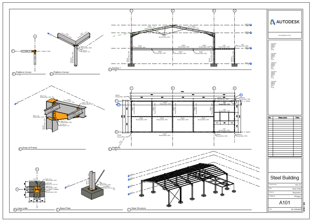
Structural detail drawings
- Foundation details such as footings, piles, grade beams, and waterproofing.
- Beam–column connections, slab edges, and reinforcement anchorage.
- Expansion joints, movement joints, and structural bracing details.
- Concrete, steel, timber, or composite connections with bolts, welds, or plates.
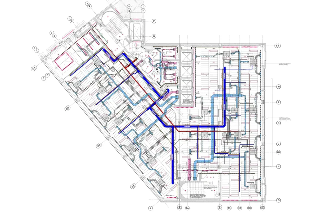
MEP detail drawings
- Pipe routing details, supports, brackets, and penetration sleeves through walls and slabs.
- Duct connections to diffusers, grilles, and equipment with clear space requirements.
- Cable tray details, containment supports, and earthing connections.
- Plant room details showing coordinated arrangement of pumps, chillers, or AHUs.
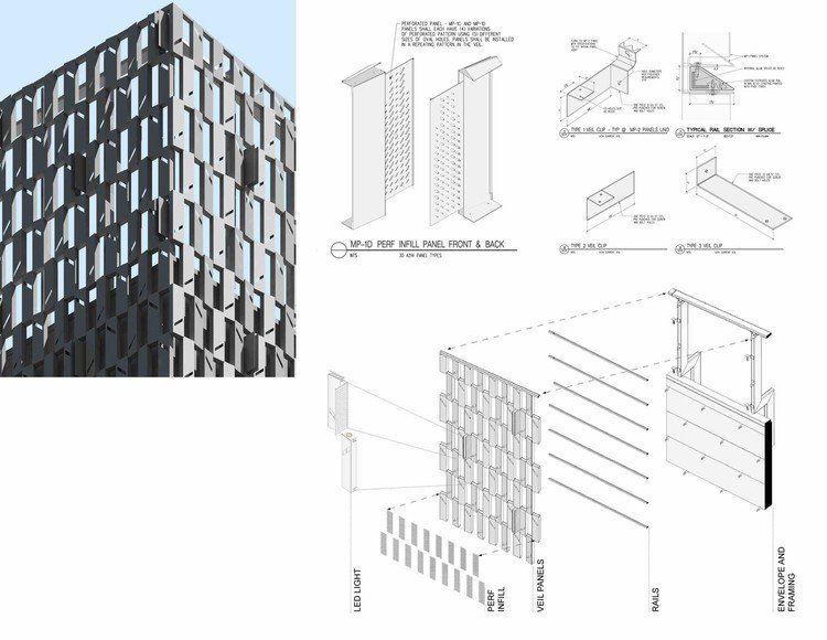
façade detail drawings
- Curtain wall systems and cladding support structures with fixing brackets.
- Balcony edge details, balustrades, and handrails with safety dimensions.
- Waterproofing terminations at terraces, podiums, and wet areas.
- Landscape details such as paving build-ups, planters, and surface drainage.
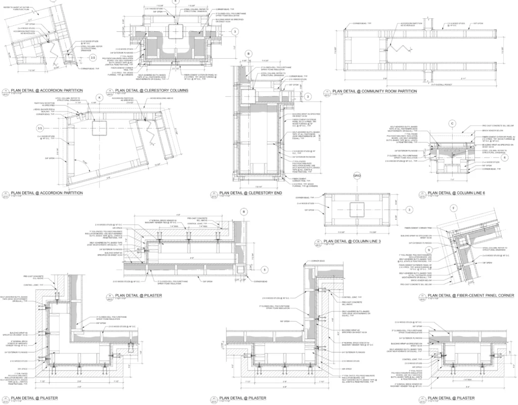
Key Information in a Building Details Drawing
- Clear and consistent dimensions including thicknesses, lengths, heights, and slopes.
- Levels and reference datums so the detail aligns correctly with the overall building grid.
- Complete material descriptions, including type, grade, finish, and performance requirements.
- Layer build-ups shown in the correct sequence: structure, insulation, membranes, screeds, and finishes.
- Annotation and notes explaining fixing methods, fasteners, sealants, and tolerances.
- Symbols and hatching that follow standard conventions, making drawings easy to read.
- Cross-references to related plans, sections, schedules, and specifications.
- Revision information and dates so the construction team knows the latest approved version.

Best Practices for Creating Building Details Drawings
- Use Revit scales like 1:10/1:5; maintain consistent line weights and layers.
- Add concise notes; group logically by construction sequence.
- Leverage Revit detail components, insulation tools, and families; verify against specs.
- Review with contractors for buildability; prefer “model + 2D” hybrids.
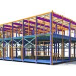
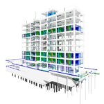
BIM, CAD, and Modern Detailing Workflows
- Revit generates details from coordinated 3D models, auto-updating views on changes.
- Clash detection via Navisworks flags conflicts early; BIM execution plans standardize naming/sharing.
- Autodesk AEC Collection enables cloud collaboration, version control, and fabrication detailing.
How to Create Accurate Building Details Drawings
Creating accurate building details drawings starts with understanding the project scope and the exact construction problem the detail must solve. A good detail drawing should show how materials, components, and connections work together clearly enough for builders to follow without confusion.
- Start with the project scope. Define the purpose of the detail, the building element involved, and the level of information needed. This helps you avoid unnecessary complexity and keeps the drawing focused on what construction teams actually need.
- Study existing precedents. Review similar details from completed projects, standard libraries, or trusted references before drawing from scratch. This can save time and helps you build on proven solutions instead of guessing at assemblies.
- Understand material junctions. Learn how walls, floors, roofs, windows, and structural elements connect in real life. Accurate details depend on knowing how materials meet, overlap, seal, and support each other.
- Use precise dimensions and scale. Include exact measurements for thicknesses, openings, clearances, and connection points, and draw the detail at a scale that makes the critical information readable. Accuracy in dimensioning is essential for construction fit and coordination.
- Keep conventions consistent. Use the same line weights, symbols, labels, hatches, and notation style throughout the set. Consistency improves readability and reduces the chance of misinterpretation on site.
- Add only the necessary information. Show the materials, layers, fixings, and interfaces that matter to the detail, but avoid clutter. The goal is clarity, not overload.
- Review for coordination and buildability. Check the detail against architectural, structural, and MEP requirements, and look for clashes or missing information before issuing it. BIM workflows and multidisciplinary review can significantly reduce errors and rework.
- Finalize with annotations and revisions. Make sure every detail has a clear title, reference number, scale, notes, and revision history. This makes the drawing easier to track and use across the project lifecycle.
Common Mistakes to Avoid in Detail Drawings
- Missing key dimensions, such as slab thickness, cover to reinforcement, or sill heights.
- Inconsistent information between a building details drawing and the related plan or section.
- Vague material descriptions like “insulation” or “membrane” without specifying type or performance.
- Over-detailed drawings that show unnecessary information, making it hard to see the critical elements.
- Using non-standard symbols or abbreviations that are not explained in the legend.
- Failing to coordinate MEP penetrations with structural elements, leading to site conflicts.
- Ignoring constructability, resulting in details that are difficult or expensive to build in reality.
💡 Pro Tip: Building details drawings are a critical component of complete BIM documentation that connects design models with construction execution.
Learn how to structure comprehensive project documentation for seamless coordination.
Conclusion
Building details drawing are essential for clear communication, accurate construction, and fewer site errors. When prepared carefully, they help turn design ideas into successful project execution.
FAQ About Building Details Drawing
1. What scale should building detail drawings use in Revit?
Use 1:10, 1:5, or 1:2 scales in Autodesk Revit to clearly show materials, fixings, and layer build-ups without overcrowding.
2. How does Revit improve detail drawing coordination?
Revit generates details from 3D models with automatic updates and Navisworks clash detection, ensuring architectural, structural, and MEP alignment.
3. What’s the difference between plans and detail drawings?
Plans show overall layout at small scales (1:100); detail drawings zoom into junctions (1:10+) with materials, thicknesses, and construction methods.
4. Why avoid “scale-only” dimensions in details?
Construction teams must measure precisely from drawings—never from scale—since printed outputs and site conditions vary. Always show explicit dimensions.
5. How do BIM workflows prevent common detailing errors?
Revit’s model-based approach catches missing dimensions, uncoordinated penetrations, and revision issues through automated checks and version tracking.
6. What is the purpose of a detail drawing?
The purpose of a detail drawing is to show a small part of a building or object at a larger scale with exact dimensions and construction information so it can be built correctly.
7. What is a detail drawing?
A detail drawing is a large-scale drawing of a specific part of a building, machine, or structure that shows important construction details.
8.What is the meaning of detail drawing?
A detail drawing means a drawing that focuses on one small part of a design and gives clear technical information about how it is made or assembled.
9. What is the difference between construction drawing and detail drawing?
Construction drawings show the overall project and guide the full building process, while detail drawings focus on one specific part and explain exactly how it should be built.