


Electric Substation Construction is the end-to-end process of building the facility that steps voltage up or down as power moves through the grid — transformers, switchgear, busbars, protection and control, inside a secured compound. In Saudi Arabia and the UAE that work runs at different voltage levels, under different utility approval regimes, and at a scale most international guides do not describe. This guide covers the seven construction phases, the AIS versus GIS decision, how SEC and DEWA prequalification actually shapes who can bid, what IEC 61850 means for your documentation, and where BIM coordination earns its place on a substation project.
- What substation construction involves
- Voltage levels in Saudi Arabia and the UAE
- AIS, GIS and hybrid: the footprint decision
- The seven construction phases
- The GCC substation market in 2026
- How SEC and DEWA prequalification shapes the market
- Civil and structural scope
- Electrical installation sequence
- Protection, control and IEC 61850
- Where BIM fits on a substation project
- Testing, commissioning and energisation
- Cut-over: building beside a live substation
- Programme and risk: where projects slip
- Frequently asked questions
What Is Electric Substation Construction?
A substation is the node where voltage changes. Generation delivers power at one level, transmission moves it at another, and distribution delivers it at a third — and a substation sits at each transition, housing the transformers, switchgear, busbars, protection relays and control systems that make the change safely and switchably.
Substation construction is the delivery of that facility end to end: site selection and acquisition, engineering design, permitting and utility approval, equipment procurement, civil and structural works, electrical installation, then testing, commissioning and energisation. A typical project runs somewhere between roughly eight and twenty-four months depending on voltage level, footprint, technology and how much of the work sits on the critical path behind long-lead equipment.
What makes these projects distinctive is the concentration of interfaces. A substation is a small site carrying a dense mix of heavy civil work, structural steel, high-voltage equipment with tight tolerances, thousands of cable terminations, and a control and protection system with its own data architecture — all of it delivered by different specialists into the same compound.
Voltage Levels in Saudi Arabia and the UAE
Most English-language guides to substation construction are written around North American practice and quote voltage levels that do not exist in this region. If you are working in the Gulf, the first thing to get right is which network you are on.
| Network | Transmission | Sub-transmission | Distribution |
|---|---|---|---|
| Saudi Arabia (SEC / National Grid SA) | 380 kV | 132 kV, and 230 / 115 / 69 kV in parts of the network | 13.8 kV |
| Dubai (DEWA) | 400 kV | 132 kV | 11 kV |
The terminology differs too. In Saudi practice a major transmission substation is commonly referred to as a BSP — a bulk supply point — and tenders are issued against numbered BSP references rather than descriptive names. Getting the vocabulary right matters when you are reading a scope of works or a prequalification notice.
AIS, GIS and Hybrid: The Footprint Decision
The single biggest technology decision on a substation project, and the one that drives site size, programme and cost.
Air-insulated switchgear (AIS)
Atmospheric air provides the insulation between live parts. Because air has relatively low dielectric strength, live components need large physical clearances, so an AIS substation occupies a substantial footprint with equipment mounted on steel or concrete structures in the open. Equipment cost is lower, installation is straightforward, inspection and maintenance are visually accessible, and the open layout makes future expansion easier.
Gas-insulated switchgear (GIS)
Sulphur hexafluoride (SF6) gas, sealed inside metal enclosures, provides the insulation. SF6 has far higher dielectric strength than air, so clearances shrink dramatically and busbars, circuit breakers and disconnectors sit in metal-clad compartments rather than spread across a yard. A 132 kV GIS installation can occupy a small fraction of the land a conventional air-insulated equivalent would need.
The second advantage is programme. GIS modules arrive factory-assembled and factory-tested, so site work becomes assembly and gas integrity management rather than build-and-test. There is documented experience of assembly and installation time being substantially reduced by off-site preassembly, and of commissioning risk falling because site teams have fewer items to test and troubleshoot.
Hybrid arrangements
Not every project is all-or-nothing. Hybrid configurations enclose the space-critical elements — typically busbars and selector disconnectors — in metal cladding while the feeder equipment remains conventional AIS. Large SEC tender packages have included 380 kV hybrid GIS alongside full GIS at both 380 kV and 132 kV in the same substation.
| AIS | GIS | |
|---|---|---|
| Insulating medium | Atmospheric air | SF6 in sealed enclosures |
| Footprint | Large | Far smaller |
| Equipment cost | Lower | Higher |
| Site installation time | Longer on site | Shorter — factory-assembled modules |
| Best suited to | Open sites where land is available | Constrained urban sites, industrial plots, indoor installations |
| Maintenance access | Open, visually inspectable | Enclosed; gas handling expertise required |
| Expansion | Flexible | Requires planned provision |
| Environmental consideration | None specific to insulation | SF6 is a potent greenhouse gas; handling, leak management and reporting apply, and SF6-free alternatives are increasingly available |
In dense urban environments across the Gulf — and on developments where land value is high — GIS is frequently the default rather than the premium option, because the land saved is worth more than the equipment premium.
The Seven Construction Phases
1. Site selection and acquisition
Driven by where the load is, where the incoming circuits can reach, and what land is available. Access for transformer delivery is a genuine constraint: a large power transformer is an abnormal load with route, bridge and turning-circle implications that need checking long before the order is placed.
2. Engineering design
Single-line diagram, layout and clearances, earthing and lightning protection, civil and structural design, cable routing, protection and control philosophy, and the auxiliary systems. This is where medium and high voltage electrical design — transformer sizing, MV cable routing, load and short-circuit analysis and protection coordination studies — sets the constraints everything else works within. On utility projects the design must satisfy the utility’s own standards in addition to the applicable IEC standards.
3. Permitting and utility approval
Utility technical approval, municipal permits, and any environmental or authority consents. This phase is frequently underestimated in the programme, and it gates procurement of anything that has to be approved before it is ordered.
4. Equipment procurement
Power transformers, GIS bays, circuit breakers, reactors, protection relays and control systems are all long-lead items. Procurement usually sits on the critical path from the moment the design freezes, and manufacturing slots for large transformers in particular can dominate the programme.
5. Civil and structural works
Earthworks and grading, foundations, transformer plinths with oil containment, cable trenches and ducts, control building, roads, drainage and perimeter security. The earthing grid is installed during this phase and is effectively irrecoverable afterwards.
6. Electrical installation
Equipment erection, GIS assembly, transformer installation and oil processing, busbar work, cable pulling and termination, control and relay panel installation, and the auxiliary AC and DC systems.
7. Testing, commissioning and energisation
Factory acceptance tests, site acceptance tests, pre-commissioning checks, protection and functional testing of the automation system, then energisation and handover to the utility.
Working on a substation package in Saudi Arabia or the UAE?
AMC Engineer delivers medium and high voltage design — substation design, transformer sizing, MV cable routing and protection coordination studies — alongside fully coordinated Revit MEP models at LOD 300–400.
The GCC Substation Market in 2026
Most guides to substation construction contain no market data at all. Here is what the published position actually looks like in the region, using Dubai as the clearest example because DEWA reports its transmission programme publicly.
| Indicator (Dubai / DEWA) | Reported position |
|---|---|
| Contracts awarded for 132 kV substations and transmission cable projects | 21 contracts, approximately AED 3 billion |
| Saih Al Dahal 400/132 kV transmission substation, in the Mohammed bin Rashid Al Maktoum Solar Park | 2,000 MVA transformation capacity, approximately AED 630 million, with around 117 km of 400 kV overhead transmission lines |
| Currently under development | 65 new 132 kV substations and one 400 kV substation |
| Planned tenders over the following three years | More than 30 additional 132 kV substations, approximately 340 km of underground transmission cables, and two further 400 kV substations |
| Transmission network at the end of H1 2026 | 402 transmission substations — 28 at 400 kV and 374 at 132 kV |
The strategic framing DEWA gives this programme is capacity and resilience for continued economic and urban growth, aligned with the Dubai Economic Agenda D33.
Saudi Arabia’s picture is structured differently. Rather than a single publicly reported pipeline figure, the market is visible through the tender stream: SEC issues bulk supply point packages on a lump-sum turnkey basis, each covering design, supply, installation, testing and commissioning of the complete substation. A single large package can include 380 kV GIS, 132 kV GIS, 380 kV hybrid GIS, power transformers, shunt and line reactors, full protection, metering, control and communication equipment, SCADA, and the civil and electro-mechanical works — with the substation automation system specified to IEC 61850.
How SEC and DEWA Prequalification Shapes the Market
This is the commercial reality no technical guide covers, and it determines who can actually bid.
Utilities in the region do not award high-voltage substation work openly. Contractors are prequalified, and in Saudi Arabia the prequalification is tiered by voltage level: a contractor may be prequalified with SEC for substations up to 132 kV without being prequalified for 380 kV work. Those are effectively two different markets with two different competitor sets.
Three practical consequences follow:
- Experience is not transferable upward. A strong 132 kV record does not open the 380 kV market. Moving up a tier is a deliberate commercial programme, not a natural progression.
- Delivery is usually lump-sum turnkey. The main contractor carries design, supply, construction, testing and commissioning as one package, which means the engineering and documentation load sits inside the contractor’s scope rather than with a separate consultant.
- Specialist scopes flow down. Because LSTK packages are large and multidisciplinary, main contractors routinely subcontract design engineering, detailing, coordination and documentation. Regional design consultancies operate specifically as engineering subcontractors to the major EPC names on utility projects — which is where much of the substation engineering work actually sits.
Civil and Structural Scope
The civil package is larger than the equipment photographs suggest, and several elements are effectively irreversible once concrete is poured.
- Earthworks and platform. Grading, compaction and levels, with drainage designed for the site’s actual conditions rather than a standard detail.
- The earthing grid. Buried conductor mesh, rods and connections, installed before backfill. Earthing performance is a safety function, and remedial work after the platform is complete is disproportionately expensive.
- Transformer foundations and oil containment. Heavy plinths designed for equipment mass and seismic requirements, with bunds, oil separators and firefighting provision. Rail or skid arrangements for transformer positioning need to be designed in.
- Equipment support structures. Steel gantries and supports for AIS yards; slab and plinth arrangements for GIS halls.
- Cable trenches, ducts and pits. The routes that carry every power and control cable in the substation. Congestion here is a common source of late rework.
- Control building. Housing relay and control panels, auxiliary systems, battery rooms and the substation automation equipment, with its own HVAC, fire and security requirements.
- Roads, security and perimeter. Access for abnormal loads, perimeter fencing, gates, lighting and surveillance.
Foundation and structural reinforcement on transformer plinths and equipment supports is substantial and heavily detailed — see our guide to rebar detailing for how those packages are scheduled and coordinated.
Electrical Installation Sequence
Once the structure is up, electrical work begins in a fairly consistent order.
Early enabling work
Cable tray and containment systems, preliminary earthing connections, and temporary lighting so crews can work safely inside the building and the yard.
GIS installation
The defining activity on a modern high-voltage substation. GIS sections arrive factory-tested and sealed, and the site task is correct assembly and maintenance of gas integrity throughout — a precision activity with cleanliness, moisture and pressure requirements that do not tolerate improvisation. Gas handling, evacuation, filling and leak testing are specialist operations with their own environmental controls.
Transformer installation
Positioning, assembly of radiators and bushings, oil filling and processing, and testing. Oil processing in particular is time-dependent and cannot be compressed.
Cabling and termination
The most labour-intensive phase. A modern substation carries a large volume of power, control and communication cable between GIS, local control cubicles, the control room and auxiliary systems. Two practices distinguish good work from work that will cause problems later:
- Glanding. Every cable entering a panel gets a proper gland, providing strain relief and preserving the panel’s ingress protection rating against dust and moisture — a meaningful consideration in this region’s conditions.
- Dressing. Cables routed and secured inside panels in an orderly, labelled, maintainable arrangement. Poor dressing does not fail immediately; it fails five years later when someone has to trace a circuit under outage pressure.
Panels and auxiliary systems
Protection and control panel installation, marshalling, the AC and DC auxiliary supplies, battery systems and chargers.
Protection, Control and IEC 61850
The substation automation system (SAS) is what turns a collection of equipment into a controllable, monitorable node on the grid — and on utility projects in the region it is routinely specified to IEC 61850.
IEC 61850 standardises how devices in a substation describe themselves and communicate. It brings three things that matter beyond the protection engineering itself:
- A defined data model. Equipment functions are described in a standard structure, so devices from different manufacturers can interoperate.
- Engineering as configuration files. The system is described in standardised configuration files that become project deliverables in their own right — documentation, not just settings.
- Event archiving and secure remote access. The basis for remote maintenance, troubleshooting and post-event analysis without a site visit.
The documentation consequence is often underestimated at tender stage. An IEC 61850 system produces a structured information deliverable that has to be version-controlled, reviewed and handed over alongside the drawings — and it is generated by a different specialist team from the one producing the civil and electrical documentation. Keeping both streams in one controlled environment is a project management problem before it is a technical one.
Where BIM Fits on a Substation Project
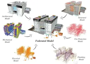
Substations are treated as electrical projects, so they are often documented in 2D long after buildings of comparable complexity moved to coordinated models — even though electrical BIM coordination of cable trays, conduits and equipment placement is now routine on buildings of far lower complexity. That is a gap, because the interfaces that cause substation rework are exactly the ones a federated model exists to catch.
The interfaces that actually cause problems
- Cable routes against structure. Trenches, ducts, risers and tray routes competing with foundations, plinths and building structure.
- Equipment access and clearances. Withdrawal space for breakers, maintenance access to GIS bays, transformer removal routes, crane access — all of them spatial requirements that are invisible on a single-line diagram.
- Control building services. HVAC, fire suppression, lighting and small power competing with cable containment above the panels.
- Embeds and penetrations. Cast-in items, sleeves and openings through walls and slabs, which must be right before concrete is poured because retrofitting them is expensive and sometimes structurally unacceptable.
- Earthing runs. Buried and above-ground conductor routes crossing everything else.
What coordination delivers here
Running clash detection across a federated civil, structural, electrical and building-services model catches these before they become a site instruction. On a lump-sum turnkey package, where the contractor absorbs the cost of every interface discovered late, that shift is directly commercial rather than merely tidy.
Two further points specific to substations:
- Model development level matters. Clash detection against models without supports, brackets and containment produces a clean report and a congested control building. Coordination sign-off belongs against LOD 350 or better — see our guide to BIM levels of development.
- As-built models have an operational life. A substation is a maintained asset for decades. An accurate as-built model with equipment data attached supports outage planning, replacement studies and future extension — and extension is the normal condition for a substation, not the exception.
Shop drawings, embedded item schedules and fabrication documentation follow the same submittal discipline as any other project — see our guide to shop drawings in construction for the review cycle, and to the construction bill of materials for the procurement side.
Reducing engineering risk inside a lump-sum turnkey package?
From load analysis and single line diagram development through 3D modelling, multi-discipline coordination, detailed design documentation and commissioning support — one team across the electrical scope.
Testing, Commissioning and Energisation
Commissioning is a sequence, and each stage depends on the one before it.
- Factory acceptance testing. Equipment tested at the manufacturer’s works before shipment, usually witnessed. Failures caught here are cheap; the same failure caught on site is not.
- Site acceptance and pre-commissioning. Verification that equipment arrived undamaged and is correctly installed — insulation testing, gas quality and pressure checks on GIS, transformer oil testing, earthing continuity and resistance measurement.
- Protection and functional testing. Relay settings applied and verified, protection schemes tested end to end, interlocks proven, automation system functions and communications checked against the design.
- Energisation. Staged application of voltage under a controlled procedure agreed with the utility, followed by observation, load transfer and handover.
One of the underappreciated advantages of GIS is here: because modules arrive factory-assembled and factory-tested, site teams have fewer items to test and troubleshoot, which reduces both duration and the risk of an unexpected problem surfacing at the very end of the programme — the point at which delay is most expensive.
Cut-over: Building Beside a Live Substation
A large share of substation work is not greenfield. It is extension, replacement or retrofit of a facility that must keep supplying load throughout — and that changes everything about how the work is planned.
The core challenge: you are constructing within the safety envelope of energised equipment, and the existing supply cannot simply be switched off while you do it.
What a credible cut-over plan contains:
- A staged construction sequence, documented iteration by iteration, showing the physical state of the site at each step and what remains energised.
- Temporary supply arrangements so the existing installation stays fed while the new facility is built and progressively brought into service.
- Circuit-by-circuit commissioning rather than a single changeover, so risk is taken in small increments and each step is reversible.
- Outage windows agreed with the utility, which are typically short, scarce, and scheduled around network conditions rather than around your programme.
- Safety demarcation between construction areas and live areas, with permit-to-work discipline that everyone on site actually follows.
Cut-over planning is where substation projects most often lose time, because the sequence is constrained by the network rather than by construction logic. It belongs in the programme from day one, not as a commissioning-phase detail.
Programme and Risk: Where Projects Slip
| Risk | How it shows up | Mitigation |
|---|---|---|
| Long-lead equipment | Power transformers and GIS bays dominating the critical path from design freeze | Order against frozen design as early as the contract allows; track manufacturing slots, not just delivery dates |
| Transformer transport | An abnormal load that cannot physically reach the site | Route survey before the order is placed, not before delivery |
| Utility approval cycles | Design or submittal approvals gating procurement | Build the submittal programme backwards from procurement dates and track it as a register |
| Land and access | Site handover later than assumed at tender | Confirm access and possession dates contractually, with a clear position on delay |
| Outage availability | Cut-over windows scarce and short | Agree outage sequence with the utility early; design the works to suit the windows available |
| Interface coordination | Civil, structural, electrical and control scopes clashing on site | Federated model coordination before construction, with embeds and penetrations resolved before pours |
| Documentation and IEC 61850 deliverables | Configuration and as-built deliverables incomplete at handover | Treat them as scheduled deliverables with owners and dates, not an end-of-project task |
| Commissioning surprises | Problems surfacing at the most expensive moment in the programme | Rigorous FAT, and technology choices that shift testing off site where practical |
Frequently Asked Questions
What is substation construction?
Substation construction is the end-to-end process of building an electrical substation — the secured facility of transformers, switchgear, busbars and protection equipment that steps voltage up or down as power moves through the grid. It covers site selection, engineering design, permitting and utility approval, equipment procurement, civil and structural works, electrical installation, and testing and commissioning before energisation.
How long does it take to build a substation?
Typically somewhere between around eight and twenty-four months, depending on voltage level, footprint, technology and how much of the programme sits behind long-lead equipment. Power transformers and GIS bays frequently dominate the critical path, so procurement lead time often determines the schedule more than construction duration does.
What voltage levels are used in Saudi Arabia and the UAE?
In Saudi Arabia the transmission level is 380 kV, with 132 kV sub-transmission — and 230, 115 and 69 kV in parts of the network — and 13.8 kV distribution. In Dubai, DEWA operates at 400 kV transmission, 132 kV sub-transmission and 11 kV distribution. Major Saudi transmission substations are commonly referred to as bulk supply points, or BSPs.
What is the difference between an AIS and a GIS substation?
An air-insulated substation uses atmospheric air as the insulating medium between live parts, which requires large clearances and therefore a large footprint, with equipment mounted in the open. A gas-insulated substation uses SF6 gas inside sealed metal enclosures, which allows far smaller clearances and a dramatically smaller footprint. GIS costs more per unit of equipment but installs faster on site because modules arrive factory-assembled and factory-tested.
When should GIS be chosen over AIS?
Where land is constrained or expensive, where the substation must be indoors or within an industrial or urban site, where the environment makes open equipment harder to maintain, or where programme pressure favours factory assembly over site build. Where land is available and expansion flexibility matters more than footprint, AIS remains a reasonable choice. Hybrid arrangements enclose only the space-critical elements and are common on large transmission packages.
What is a BSP in Saudi substation projects?
A bulk supply point — a major transmission substation on the SEC network. SEC tenders are typically issued against numbered BSP references and delivered on a lump-sum turnkey basis covering design, supply, installation, testing and commissioning of the complete facility including civil and electro-mechanical works.
How does SEC prequalification work for substation contractors?
SEC prequalifies contractors by voltage tier, so a contractor may be prequalified for substations up to 132 kV without being prequalified for 380 kV work. These are effectively two separate markets with different competitor sets, and experience at the lower tier does not automatically qualify a contractor for the higher one. Work is generally awarded on a lump-sum turnkey basis to prequalified contractors rather than through open tender.
What is IEC 61850 and why does it matter for substation projects?
IEC 61850 is the international standard for substation automation communications and data modelling. It defines how devices describe themselves and communicate, enabling equipment from different manufacturers to interoperate, and it produces standardised configuration files that are project deliverables in their own right. Utility substation tenders in the region routinely specify substation automation systems based on it, which means the documentation and version control obligations extend beyond drawings.
What does cut-over mean on a substation project?
Cut-over is the process of transferring supply from an existing installation to a new or extended one while keeping load served throughout. It requires a staged construction sequence, temporary supply arrangements, circuit-by-circuit commissioning, agreed outage windows with the utility, and strict safety demarcation between construction and energised areas. It is one of the most common sources of programme delay because the sequence is dictated by network conditions rather than construction logic.
Why use BIM on a substation project?
Because the interfaces that cause substation rework are spatial ones a single-line diagram cannot show: cable trench and tray routes against foundations and structure, equipment withdrawal and maintenance clearances, control building services against containment, cast-in embeds and penetrations, and earthing runs crossing everything. Federating civil, structural, electrical and building-services models and running clash detection resolves these before they become site instructions — which matters commercially on a lump-sum package where the contractor absorbs late interface costs.
What LOD is needed to coordinate a substation model?
LOD 350 or better for coordination sign-off. Below that, supports, brackets, containment and access zones are not modelled, so clash detection produces a clean report against a control building that will still be congested when it is built. Earlier indicative checks at lower development levels are useful for gross routing, but they are not a coordination sign-off.
Is SF6 being phased out in gas-insulated switchgear?
SF6 is a potent greenhouse gas, so its handling, leak management and reporting are subject to environmental controls, and the industry has been developing and deploying alternative insulating gases and SF6-free switchgear. Whether an alternative is appropriate on a given project depends on the utility’s own standards and approved equipment list, which should be confirmed at design stage rather than assumed.
Conclusion
Substation construction rewards planning far more than it rewards speed on site. The schedule is usually set by transformer and GIS manufacturing slots, the sequence is often set by outage windows the utility controls, and the cost exposure sits with whoever is holding the lump-sum package when an interface problem is discovered late.
For projects in Saudi Arabia and the UAE, three things separate the teams that deliver predictably from the ones that do not: getting the voltage level, utility standards and prequalification position right before bidding; treating utility approvals and long-lead procurement as the real critical path; and resolving the civil, structural, electrical and control interfaces in a coordinated model before they meet in a control building that is already too small for all of them.
Let’s resolve the electrical scope before it reaches site.
AMC Engineer provides MV and HV design, power distribution and protection coordination, electrical BIM modelling and clash detection for contractors and consultancies delivering power and infrastructure projects across Saudi Arabia and the UAE.
