A LiDAR system measures distance by firing laser pulses and timing how long the reflection takes to return. In construction that produces a point cloud — millions of measured coordinates describing a building exactly as it stands today, not as it was drawn. The value is not the scan; it is what happens afterwards. This guide covers how LiDAR works, which system types matter for buildings, what a point cloud actually contains, the scan-to-BIM workflow that turns it into a usable model, what accuracy you can honestly promise, and where the technology earns its place on projects in Saudi Arabia and the UAE.
- What a LiDAR system is
- Is LiDAR the same as laser scanning?
- Types of LiDAR systems
- What a point cloud actually is
- The scan-to-BIM workflow
- Accuracy: what you can and cannot promise
- Scan to BIM and level of development
- What scanning misses
- Where it earns its place on Gulf projects
- Site conditions in the Gulf
- As-built deliverables and authority submission
- Equipment and software
- Seven scan-to-BIM failures
- Frequently asked questions
What Is a LiDAR System?
LiDAR System stands for Light Detection and Ranging. The principle is simple: the instrument emits a laser pulse toward a surface, the pulse reflects, and the system measures the time of flight — how long the reflection takes to return. Because the speed of light is known, that time converts directly into a distance. Repeat it millions of times across a scanned field of view and you have a dense three-dimensional record of everything the laser could see.
A working LiDAR system is not just a laser. It integrates three technologies:
- The laser rangefinder, which emits pulses and measures return time.
- Positioning — GPS or another global navigation system — which establishes where the instrument is.
- An inertial measurement unit (IMU), which tracks the instrument’s orientation and motion so each measurement can be correctly placed in space.
Compared with conventional radar, LiDAR offers higher resolution, better concealment and stronger resistance to interference — which is why it has spread from atmospheric research in the 1960s into surveying, autonomous vehicles, forestry, archaeology and, relevant here, the built environment.
Is LiDAR System the Same as Laser Scanning?
Not quite, and the distinction is worth getting right because the terms are used interchangeably on projects.
LiDAR describes the underlying measurement method — ranging by laser time of flight. Laser scanning describes the practice of using that method to systematically capture a surface, object or space in order to produce a dimensional record. Every terrestrial laser scanner used on a building is a LiDAR instrument; not every LiDAR application is laser scanning in the surveying sense.
In practice, when a construction professional says “we’re doing a LiDAR survey” and “we’re laser scanning the building”, they mean the same activity. The reason to be precise is that searching for LiDAR information will surface a great deal of material about autonomous vehicles, MEMS mirrors and solid-state beam steering — genuinely interesting engineering, and entirely irrelevant to capturing an existing building.
Type of LiDAR System
| Category | Type | How it is deployed | Relevance to buildings |
|---|---|---|---|
| Airborne | Topographic | Aircraft or drone, near-infrared laser | Terrain modelling, site context, corridor mapping. Not for building interiors |
| Bathymetric | Aircraft, green laser that penetrates water | Coastal and marine works only | |
| Terrestrial | Static | Tripod-mounted, scanning from fixed positions | The standard for buildings. Highest accuracy and density |
| Mobile | Vehicle, trolley or backpack mounted | Roads, tunnels, large corridors, rapid coverage of long linear assets | |
| Handheld / SLAM | — | Walked through the space, self-localising | Fast, lower accuracy. Good for volumetric capture and progress records |
| Drone / UAV | — | Small LiDAR payload on a UAV | Roofs, facades, large sites, areas unsafe to access on foot |
For most building projects the answer is a static terrestrial scanner, sometimes supplemented by handheld capture for areas where speed matters more than millimetre accuracy, and by drone capture for roofs and facades.
Have a point cloud and need a model from it?
AMC Engineer converts point cloud data into coordinated LOD 300–500 BIM models across Architecture, Structure, MEP, Electrical, Infrastructure and Landscape — with a free LOD 200 sample from your own data in 24 hours.
What a Point Cloud Actually Is
This is the most consequential misunderstanding in the whole subject, and it causes more disappointed clients than any technical limitation.
A point cloud is a set of measured points. Each point carries an X, Y and Z coordinate, an intensity value describing how strongly the laser returned from that surface, and often an RGB colour value taken from an integrated camera. A building scan produces hundreds of millions of them.
A point cloud is not a model. It contains no walls, no doors, no ducts, no rooms. It has no idea that a particular cluster of points is a column and another is a pipe. It is an extremely accurate measurement of surfaces, and nothing more.
Everything useful downstream — a Revit model, an as-built drawing set, a quantity takeoff, a clash check against a new design — requires someone to interpret those points and build modelled elements from them. That interpretation is the actual work, and it is where the cost and the schedule sit.
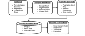
The Scan-to-BIM Workflow
- Define the purpose and the deliverable. What decision will the model support? A model for space planning, a model for MEP retrofit design, and a model for heritage documentation are three different scopes at three different costs. This step determines everything after it.
- Plan the survey. Scan positions, target placement, coverage overlap, access requirements, permits, and the areas that must be reached. A survey planned around the deliverable produces usable data; a survey planned around convenience produces gaps discovered during modelling.
- Capture. Execute the scans, with enough overlap between positions for reliable registration and enough coverage that critical elements are seen from more than one angle.
- Register. Align the individual scans into one coherent point cloud, using targets or cloud-to-cloud matching. Registration quality is checked and reported — it is a measurable output, not a feeling.
- Clean and process. Remove noise, moving objects, reflections and points outside the area of interest, then reduce the cloud to a workable density.
- Georeference and orient. Place the cloud in the project coordinate system with the correct origin, orientation and levels, so it aligns with the design models it will be used against.
- Model. Build modelled elements from the cloud in the authoring tool, to the agreed level of development, with the agreed classification and parameters.
- Verify and deliver. Check the model back against the cloud — deviation checking rather than visual inspection — then issue the model, the drawings derived from it, and a report stating the accuracy achieved and the assumptions made.
Steps 1 and 8 are the two most often skipped, and they are the two that determine whether anyone can rely on the result.
Accuracy: What You Can and Cannot Promise
Accuracy in scan to BIM has three separate layers, and conflating them is how commitments get made that cannot be met.
| Layer | What it measures | What affects it |
|---|---|---|
| Instrument accuracy | How precisely a single measurement is made | The scanner specification, range, angle of incidence, surface reflectivity |
| Registration accuracy | How well the individual scans align into one cloud | Scan overlap, target placement, survey control, operator method |
| Model accuracy | How closely the modelled elements match the cloud | Modelling tolerance agreed, level of development, how the modeller handles irregular real-world geometry |
The third is the one clients care about and the one least often discussed. A real building is not orthogonal: walls lean, slabs deflect, columns are out of plumb. A BIM model is made of idealised elements. Somewhere between the cloud and the model, someone decides how much real-world irregularity to represent and how much to straighten — and that decision is a project agreement, not a technical default.
Scan to BIM and Level of Development
The same point cloud can produce very different models, and the cost difference between them is large.
| Level | What the model contains | Suitable for |
|---|---|---|
| LOD 200 | Generic elements with approximate size and position | Space planning, feasibility, early massing of a retrofit |
| LOD 300 | Accurate geometry, correct size and position, identified element types | Design development against existing conditions, coordination of new work |
| LOD 350 | Adds interfaces, supports, connections and access zones | Retrofit coordination where new services must thread through existing ones |
| LOD 500 | Field-verified, with asset data attached | Facility management handover and digital twin foundations |
LOD 500 deserves a note. It is defined by verification against site rather than by geometric richness, which makes scan data a natural basis for it — but only if the modelling actually reflects what was measured rather than tidying it. Our guide to BIM levels of development covers what each level supports and, importantly, what it does not.
What Scanning Misses
A laser measures what it can see. Everything else has to come from somewhere else, and pretending otherwise produces a model people trust more than they should.
- Anything concealed. Services above ceilings, inside risers, behind walls or under floors are invisible unless those areas are physically opened and scanned separately.
- Occluded zones. Areas hidden behind equipment, stored material or structure at every scan position simply have no data.
- Buried and below-ground. Foundations, drainage and underground services need different survey methods entirely.
- Material and system information. The cloud shows a surface. It does not say whether a pipe carries chilled water or fire protection, what a wall is made of, or what an item of plant is rated at.
- Reflective and transparent surfaces. Glass, polished stone, mirrors and bright metal return unreliable data, producing noise or gaps.
Where It Earns Its Place on Gulf Projects
Retrofit, refurbishment and extension
The most common case. Older buildings across Riyadh, Jeddah, Dubai and Abu Dhabi frequently have drawings that are missing, superseded or simply wrong — and decades of modifications that were never recorded. Designing new work against a scanned model rather than an old drawing set removes an entire category of on-site surprise.
Heritage documentation
Saudi Arabia and the UAE have invested substantially in heritage conservation, and scanning is well suited to it: it captures irregular historic geometry that cannot be represented by orthogonal drawings, it is non-contact, and it produces a permanent dimensional record of a structure regardless of what happens to it later.
Industrial and process facilities
Plants, refineries and utility installations are dense with pipework and equipment, poorly documented after years of modification, and expensive to shut down. Scanning captures the as-installed condition in a short access window, and modelling from it allows tie-in design to be developed without repeated site visits.
Verification during construction
Scanning at milestones — after structure, before ceilings close — and comparing against the design model catches deviation while it is still cheap to correct, and produces an evidenced progress record. It also feeds the coordination process; see our guides to BIM coordination and clash detection.
Fit-out and tenant works
In malls, offices and towers, fit-out designers routinely work against base-build drawings that do not reflect what was built. A scan of the demised area removes the guesswork before design starts.
Retrofit or fit-out against unreliable drawings?
We model existing conditions from point cloud data and coordinate new design against them — federated, clash-checked and delivered in the format your authority and your client actually require.
Site Conditions in the Gulf
Scanning in this region carries practical constraints that temperate-climate guidance does not mention.
- Dust. Airborne dust scatters the laser and settles on optics. Scanning during or after dusty conditions produces noisier data, and instrument cleaning becomes a routine part of the day rather than an occasional task.
- Heat. Equipment has operating temperature limits, and prolonged exposure in direct summer sun affects both the instrument and the operator. Air shimmer over hot surfaces can also degrade returns at longer ranges.
- Summer outdoor work restrictions. Both Saudi Arabia and the UAE restrict outdoor work during specified midday hours in the peak summer months. External scanning has to be planned around those windows, which compresses the usable working day.
- Reflective architecture. Glass curtain walling, polished stone and bright metal cladding are common regionally and are exactly the surfaces that return unreliable data. Plan for supplementary measurement on heavily glazed facades.
- Occupied and operating buildings. Scanning in live retail, hospitality or industrial environments means working around people and operations, often at night or during shutdowns, with access approvals arranged well in advance.
As-Built Deliverables and Authority Submission
Scan-derived models are frequently the basis for as-built deliverables, and in this region that increasingly means an authority-facing deliverable rather than an internal record.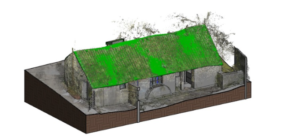
Dubai Municipality has required the use of BIM on defined categories of project since 2013, and a circular issued in October 2023 introduced BIM model submission for new building permits with IFC as the format. Abu Dhabi Municipality publishes CAD and BIM submission requirements covering naming conventions, coordinate systems and file formats, referencing ISO 19650, alongside model quality requirements addressing coordination and clash detection.
The practical implication for scan to BIM: a model built from a point cloud still has to satisfy the same classification, naming, coordinate and export requirements as any other model. Test the IFC export early rather than at submission. Our guide to BIM standards and regional mandates covers the framework.
Equipment and Software
| Stage | Typical tools | What to look for |
|---|---|---|
| Capture | Static terrestrial scanners, handheld SLAM scanners, UAV LiDAR payloads | Range, accuracy specification, integrated imaging, capture speed |
| Registration and processing | Manufacturer processing software, Autodesk ReCap | Registration reporting, cloud reduction, format export |
| Modelling | Autodesk Revit with point cloud linked, plus scan-to-BIM add-ins | Deviation checking, fitting tools, handling of large clouds |
| Coordination | Autodesk Navisworks, Autodesk Construction Cloud | Ability to federate cloud with design models for verification |
Formats worth knowing: E57 as the vendor-neutral exchange format for point clouds, RCP/RCS for Autodesk workflows, and LAS/LAZ in surveying and geospatial contexts. Agree the delivery format at the outset, since converting between them can lose attributes.
Seven Scan-to-BIM Failures
| Failure | What it causes | The fix |
|---|---|---|
| Purpose not defined before scanning | Data that does not cover what the model needed, discovered during modelling | Define the deliverable and its LOD first; plan the survey backwards from it |
| Client expects the scan to be the model | Cost and programme disputes when the modelling effort becomes visible | Set the expectation explicitly at the first meeting |
| Modelling tolerance never agreed | Argument over whether an out-of-plumb wall should have been modelled as leaning | Agree deviation tolerance and idealisation rules in writing |
| Concealed services assumed rather than surveyed | A model that looks authoritative and is partly invented | Plan opening-up surveys and non-scan inputs alongside the scan |
| Cloud not georeferenced to project coordinates | The model will not align with the design models it exists to be checked against | Georeference during processing, against project control |
| No verification against the cloud | Modelling drift nobody detects until site does | Run deviation checking before delivery and report the result |
| Export format agreed late | Attribute loss in conversion, or a deliverable the client cannot open | Agree formats and software versions at the outset |
Frequently Asked Questions
What is a LiDAR system?
LiDAR stands for Light Detection and Ranging. It measures distance by emitting laser pulses and timing how long reflections take to return, converting that time of flight into a distance. A working system integrates three technologies: the laser rangefinder, satellite positioning, and an inertial measurement unit that tracks orientation so each measurement is correctly placed in space.
Is LiDAR system the same as laser scanning?
Not exactly. LiDAR describes the measurement method — ranging by laser time of flight. Laser scanning describes the practice of using that method to systematically capture a space or object to produce a dimensional record. Every terrestrial laser scanner used on a building is a LiDAR instrument, but not every LiDAR application is laser scanning in the surveying sense.
What are the main types of LiDAR system?
Airborne systems divide into topographic, using near-infrared lasers for land surfaces, and bathymetric, using green lasers that penetrate water. Terrestrial systems divide into static, tripod-mounted scanning from fixed positions, and mobile, mounted on vehicles or trolleys. Handheld SLAM scanners and drone-mounted payloads add speed and access at lower accuracy. For buildings, static terrestrial scanning is the standard.
What is a point cloud?
A set of measured points, each carrying X, Y and Z coordinates, an intensity value describing the strength of the laser return, and often an RGB colour value. A building scan produces hundreds of millions of them. Critically, a point cloud is not a model — it contains no walls, doors or ducts and has no knowledge of what any cluster of points represents.
Does a laser scan produce a BIM model automatically?
No. The scan produces a point cloud, which is a measurement of surfaces. Turning it into a model requires someone to interpret those points and build modelled elements from them, to an agreed level of development with agreed classification and parameters. That interpretation is where most of the cost and programme sits, and the effort scales with the required LOD rather than with the size of the cloud.
How accurate is scan to BIM?
Accuracy has three layers: instrument accuracy for a single measurement, registration accuracy for how well individual scans align into one cloud, and model accuracy for how closely modelled elements match the cloud. The third is the one clients care about and it is a project agreement rather than a technical default, because real buildings are not orthogonal and someone has to decide how much irregularity to represent. Agree the tolerance in writing before work starts.
What LOD can be produced from a point cloud?
Anything from LOD 200 for space planning and feasibility, through LOD 300 for design development against existing conditions, to LOD 350 for retrofit coordination and LOD 500 for verified as-built handover. The same cloud supports all of them; the cost difference between them is substantial, which is why the deliverable should be defined before the survey is planned.
What can a laser scan not capture?
Anything the laser cannot see: services above ceilings, inside risers or behind walls; zones occluded by equipment or stored material; anything buried or below ground. It also captures no material or system information — the cloud shows a surface but does not identify what a pipe carries or what a wall is made of. Glass, polished stone and bright metal return unreliable data.
When is scanning worth it on a construction project?
Retrofit, refurbishment and extension where existing drawings are missing or wrong; heritage documentation where geometry is irregular and a permanent record is valuable; industrial and process facilities that are densely serviced and expensive to shut down; verification during construction by comparing scans at milestones against the design model; and fit-out works where base-build drawings do not reflect what was built.
How do Gulf site conditions affect laser scanning?
Airborne dust scatters the laser and settles on optics, producing noisier data and requiring routine cleaning. Heat affects both equipment operating limits and data quality through air shimmer at longer ranges. Summer outdoor work restrictions in both Saudi Arabia and the UAE compress the usable working day for external scanning. Reflective glass and polished stone facades, common regionally, return unreliable data and may need supplementary measurement.
What file formats are used for point clouds?
E57 is the vendor-neutral exchange format, RCP and RCS are used in Autodesk workflows, and LAS or LAZ are common in surveying and geospatial contexts. Agree the delivery format at the outset, since converting between formats can lose attributes such as colour or intensity.
Can a scan-derived model be submitted to an authority?
It has to meet the same requirements as any other model. Dubai Municipality introduced BIM model submission in IFC format for new building permits following a circular issued in October 2023, and Abu Dhabi Municipality publishes submission requirements covering naming, coordinate systems and file formats referencing ISO 19650, alongside model quality requirements. Test the export early rather than at submission, and confirm current requirements with the authority.
Conclusion
LiDAR system gives you an exact measurement of what exists. That is genuinely valuable, and on retrofit, heritage, industrial and fit-out work it removes a whole category of risk that drawings alone cannot.
But the scan is not the deliverable. A point cloud is hundreds of millions of measured points with no understanding of what any of them represent, and the value comes entirely from the interpretation that follows — which means defining the purpose before the survey, agreeing the modelling tolerance before the modelling, planning for what the laser cannot see, and verifying the model back against the data before anyone relies on it. Get those four right and scanning pays for itself. Skip them and you have an expensive file nobody can use.
Let’s turn your point cloud into a model you can build against.
AMC Engineer delivers scan-to-BIM modelling, federated coordination and construction documentation for contractors, consultants and asset owners across Saudi Arabia and the UAE — from LOD 200 space models to verified LOD 500 as-built deliverables.