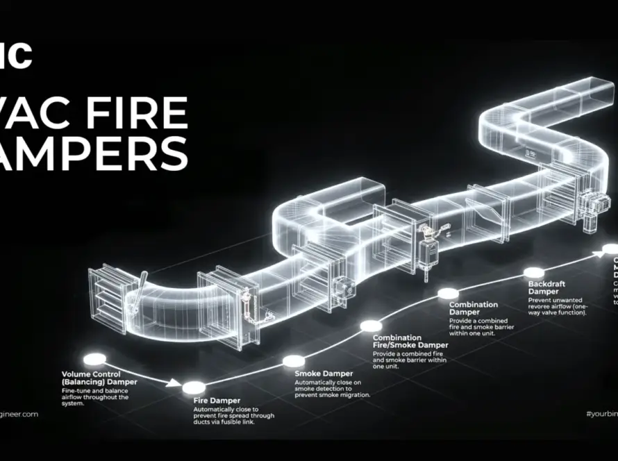
MEP Plans in Construction are the construction drawings that define how a building’s mechanical, electrical and plumbing systems are sized, routed, installed and inspected. They are permit documents before they are coordination documents, and they are the reason a ceiling void either fits every service or forces someone to lower a soffit after the slab is poured. This guide covers what a complete MEP drawing set contains, sheet numbering and symbol conventions, the Saudi Building Code and UAE authority requirements that govern them, which service moves when two systems compete for the same space, and why plenums in this region run tighter than almost anywhere else.
- What MEP plans are
- The three disciplines and what each documents
- What a complete MEP drawing set contains
- Sheet numbering and drawing conventions
- Reading MEP symbols and abbreviations
- MEP code requirements in Saudi Arabia
- MEP code requirements in the UAE
- Why Gulf plenums run tighter
- Coordination priority: which service moves
- From design drawings to composite to shop drawings
- MEP plans and the permit process
- BIM-based MEP coordination
- Seven MEP drawing set failures
- Frequently asked questions
What Are MEP Plans in Construction?
MEP Plans in Construction are the set of construction drawings that define the design, layout, routing, sizing and specification of a building’s mechanical, electrical and plumbing systems. They document what equipment is installed, where it sits, how services run between it, what size everything is, and how the three disciplines fit alongside each other and around the structure. They are prepared by MEP engineers and BIM specialists, and they are used by contractors to install, by inspectors to verify, and by the authority having jurisdiction to grant a permit.
On many projects a fourth discipline sits alongside them. MEPF or MEPFS adds fire protection and fire safety — sprinklers, standpipes, fire alarm, smoke control — which in this region carries its own review authority and is often the package with the least routing flexibility of all.
The Three Disciplines and What Each Documents
| Discipline | Systems covered | What the drawings define | Routing flexibility |
|---|---|---|---|
| Mechanical (M) | HVAC, ventilation, exhaust, chilled water, air distribution | Equipment locations and capacities, duct routes and sizes, pipe routes and sizes, plant room layouts, terminal units | Low — large sections, limited flexibility |
| Electrical (E) | Power distribution, lighting, containment, earthing, emergency systems, low voltage | Panel and switchgear locations, circuit layouts, cable tray and conduit routes, lighting layouts, riser diagrams | High — tray and conduit reroute easily |
| Plumbing (P) | Domestic water, sanitary drainage, stormwater, vents | Fixture locations, supply and drainage routes, pipe sizes, riser diagrams, floor penetrations | Mixed — pressurised pipe is flexible, gravity drainage is not |
| Fire protection (F) | Sprinklers, standpipes, pumps, fire alarm, smoke control | Head layouts and coverage, main and branch routing, pump room layout, detection and alarm devices | Low — coverage rules and authority approval constrain layout |
That last column is the one that decides coordination, and it is covered properly further down.
What a Complete MEP Drawing Set Contains
A drawing set is not just floor plans. A complete package normally includes nine categories, and packages are most often found incomplete in the last three.
1. Cover sheet and legend
General notes, the symbol legend, abbreviation list, drawing index and standard details. Symbol conventions vary between firms, which is exactly why the legend sheet exists and why it should be read before anything else in the set.
2. Floor plans
Discipline-by-discipline layouts showing equipment, routing and sizes on each level. The working drawings most people mean when they say “MEP plans”.
3. Riser diagrams
Vertical schematics showing how systems connect between floors — supply, waste and vent stacks, electrical risers, chilled water risers. Essential for verifying that pipe and duct sizes increase correctly as more load connects downstream, which a floor plan cannot show.
4. Sections and elevations
Cuts through congested areas showing vertical relationships between services, structure and ceiling. Where a plan says two services cross, the section says whether they fit.
5. Details
Enlarged views of plant rooms, shafts, connections, hangers, supports and typical installation conditions.
6. Equipment schedules
Tabulated capacities, ratings, models, electrical loads and performance data for every piece of equipment. This is what procurement orders from and what the reviewer checks compliance against.
7. Composite or coordinated layouts
All disciplines overlaid on one drawing with levels and offsets shown. This is the drawing that proves the services actually fit, and its absence is the single most common gap in an otherwise complete set.
8. Penetration drawings
Every point where a service passes through a structural element or a fire-rated barrier, with sleeve sizes, positions and firestopping. These must be issued early enough to be cast in rather than cut later.
9. As-built drawings
The final record of what was installed, including approved field changes. The basis for operation, maintenance and any future refurbishment.
Need a coordinated MEP package, not three separate ones?
AMC Engineer delivers ASHRAE load calculations, ceiling space allocation and shaft planning, LOD 300–400 Revit MEP models and Navisworks-coordinated construction documentation for projects across Saudi Arabia and the UAE.
Sheet Numbering and Drawing Conventions
Conventions vary by project and by consultant, but the underlying logic is consistent and worth knowing before you open an unfamiliar set.
| Prefix | Discipline | Typical use |
|---|---|---|
| M | Mechanical | M-001 general notes and legend, then M-101 onward for plans |
| E | Electrical | E-001 legend and symbols, then layouts, risers and schedules |
| P | Plumbing | P-001 legend, then supply, drainage and riser drawings |
| FP / FS | Fire protection / fire safety | Sprinkler layouts, standpipes, alarm and detection |
| A / S | Architectural / structural | Referenced by MEP sheets for coordination |
Two things on every sheet deserve more attention than they usually get:
- Issue status. Whether a sheet is for review, for approval, issued for construction or as-built determines what level of completeness to expect and whether it can be built from. A sheet without a clear status is a sheet nobody should install to.
- Cross-discipline references. The note listing which architectural, structural and other MEP sheets should be read alongside this one. These references are how coordination is verified during drawing review, and a set without them forces every reviewer to reconstruct the relationships from scratch.
Reading MEP Symbols and Abbreviations
MEP drawings communicate through a dense shorthand. The legend on the cover sheet governs — always — but these are the conventions you will meet most often.
| Discipline | Commonly encountered |
|---|---|
| Mechanical | Supply, return and exhaust ducts distinguished by line type or hatch; diffusers, grilles and registers; volume control and fire dampers; AHU, FCU and FAHU equipment tags; duct size annotations; airflow values |
| Electrical | Distribution boards and panels; socket outlets and switches; luminaire types by symbol; cable tray, trunking and conduit by line convention; circuit numbers and homerun arrows; earthing symbols |
| Plumbing | Cold and hot water distinguished by line type; soil, waste and vent stacks; floor drains, gullies and cleanouts; pipe size and slope annotations; fixture symbols and tags |
| Fire protection | Sprinkler heads by type and orientation; standpipes and hose reels; detectors and sounders; fire dampers at rated barriers; zone boundaries |
Common abbreviations across the three disciplines include equipment and system shorthand such as AHU, FCU, FAHU, VAV, CHW, DB, MDB, DB, MCC, CWS, HWS, SWS and FD — but the same letters can carry different meanings between consultants, which is why the legend outranks any general list, including this one.
MEP Code Requirements in Saudi Arabia
Almost every English-language guide to MEP plans references American codes. On a project in the Kingdom, the governing framework is the Saudi Building Code (SBC), and MEP drawings are reviewed against it.
| SBC part | Scope | Affects |
|---|---|---|
| SBC 401 | Electrical installations | Distribution design, circuit protection, containment, earthing, emergency systems |
| SBC 501 | Mechanical and HVAC | Ventilation rates, duct construction, equipment installation, smoke control provisions |
| SBC 701 | Plumbing and drainage | Fixture units, pipe sizing, venting, drainage and stormwater |
| SBC 801 | Fire protection | Sprinkler and standpipe provisions, detection and alarm, compartmentation — substantially NFPA-derived |
Alongside the SBC, international references are applied on most projects: ASHRAE for load calculation and ventilation, SMACNA for duct construction, NFPA for fire protection and IEC for electrical equipment. The specification decides which applies where, and drawings should carry the reference rather than leave the reviewer to infer it.
MEP Code Requirements in the UAE
There is no single federal MEP code across the Emirates, so requirements are set by a combination of federal fire regulation, emirate-level municipal standards, and utility-specific rules. On a Dubai project, an MEP set typically has to satisfy several of these at once.
- UAE Fire and Life Safety Code of Practice. The federal framework governing fire-rated construction, sprinkler and standpipe provision, smoke control, egress, and the fire-rated performance of materials including insulation and cabling. Fire-related MEP scope is reviewed by Civil Defence, and product certification references belong on the drawings.
- Dubai Municipality. Building regulations, green building requirements under Al Sa’fat, and submission standards, alongside its BIM requirements for applicable project categories.
- Abu Dhabi Department of Municipalities and Transport, with Estidama Pearl requirements affecting equipment efficiency, water fixtures and materials on rated projects.
- Utility regulations. DEWA in Dubai, and the Abu Dhabi distribution companies, publish their own regulations governing electrical installation, metering, substation rooms and connection arrangements — which constrain electrical drawings independently of the building code.
- District cooling providers. Where a building connects to district cooling rather than generating on site, the provider’s requirements govern the energy transfer station and the interface to the building system.
- Free zone and master developer authorities, many of which operate an additional design review with their own guidelines.
Working to SBC, UAE Fire Code or Civil Defence requirements?
We produce MEP documentation compliant with the applicable standards — ASHRAE load calculations, SMACNA duct construction, hydraulic and fixture unit calculations — coordinated in Revit and clash-checked in Navisworks before submission.
Why Gulf Plenums Run Tighter
The ceiling plenum is the most contested space in any building. In Saudi Arabia and the UAE it is more contested than almost anywhere else, and the reason is thermal rather than architectural.
Cooling load drives section size
A building here carries a cooling load that temperate-climate buildings do not. Moving that much heat means higher air volumes and higher chilled water flow, which means physically larger ducts, larger pipework, more fan coil and air handling units, and additional condensate drainage. Every one of those competes for the same void as the cable tray, the sprinkler network and the drainage falls.
What that changes in practice
- Ceiling void depth becomes a design constraint early. A void sized from a temperate-climate reference will not accommodate the services, and discovering that after the structural design is fixed means either lowering ceilings or losing floor-to-floor height.
- Shaft planning matters more. Vertical distribution has to be sized for larger risers, and shaft positions are effectively unchangeable once the structure is set.
- Plant room footprint grows. Larger equipment, plus regional dust loading affecting filtration and therefore air handling unit sizing, means plant rooms sized from a generic reference are tight before coordination even starts.
- Maintenance access competes with everything. Access panels, filter withdrawal space, valve access and damper access all need clear zones in a void that has none to spare.
The practical implication for the drawing set
Ceiling space allocation should happen at conceptual routing stage, not during coordination. Allocating zones by discipline — a band for ducts, a band for pipework, a band for containment — before detailed routing begins is what prevents the coordination cycle from becoming a negotiation over every metre of ceiling.
Coordination Priority: Which Service Moves
When two services want the same space, one of them has to move. Which one is not a matter of negotiation — it is a matter of physics and code, and applying the hierarchy consistently is what turns coordination from an argument into a process.
| Priority | Service | Why it has priority |
|---|---|---|
| 1 | Structure | Does not move. Everything routes around it |
| 2 | Gravity drainage — soil, waste, stormwater | Fixed falls. A drainage run cannot be lifted or dropped without breaking its gradient, and its route is set by fixture positions above and connection points below |
| 3 | Large ductwork and main duct runs | Largest sections in the void, and duct cannot be reduced without affecting airflow. Rerouting is expensive in both space and pressure loss |
| 4 | Fire protection mains and sprinkler branches | Head positions and coverage are governed by prescriptive rules and authority approval, which limits how far the network can move |
| 5 | Large pressurised pipework — chilled water, domestic supply | Can rise and fall and change direction, but size and support requirements constrain it |
| 6 | Cable tray, busbar and containment | Reroutes relatively freely, subject to bend radius, segregation and support |
| 7 | Small-bore pipe and conduit | The most flexible services in the building. These move last and absorb what is left |
From Design Drawings to Composite to Shop Drawings
MEP documentation develops through three distinct stages, and confusing them causes real problems on site.
- Design drawings are produced by the MEP consultant. They define system performance, equipment capacities, sizes and indicative routing. They communicate what the systems must achieve, not exactly how they will be installed.
- Composite or coordinated drawings overlay all disciplines with levels and offsets, proving the services fit within the available void alongside structure and around each other. This is where the coordination work actually happens.
- Shop drawings are produced by the contractor or subcontractor and show fabrication and installation detail — actual products, supports, fixings, connection methods and installation sequence. See our guide to shop drawings in construction for the submittal and approval cycle these go through.
The common failure is skipping stage two. When a contractor produces shop drawings directly from uncoordinated design drawings, the first place the conflict appears is on site, and by then two trades have already fabricated to different assumptions.
MEP Plans and the Permit Process
MEP plans are permit documents. That framing changes how a set should be prepared, because a reviewer is checking compliance rather than constructability.
What a review typically looks for:
- Ventilation rates and air distribution against the applicable mechanical code
- Electrical distribution, protection coordination and earthing against the electrical code and utility regulations
- Fixture units, pipe sizing, venting and drainage against the plumbing code
- Sprinkler coverage, standpipe provision, detection and smoke control against the fire code, reviewed by Civil Defence
- Energy and sustainability provisions where a green rating applies
- Equipment schedules that evidence the performance being claimed
Two practical points. First, fire-related packages usually carry the longest and least predictable review, so they should be submitted earliest. Second, authority comments arrive after the consultant’s, which means a package that only just cleared internal review has no float left when the authority responds.
BIM-Based MEP Coordination
MEP coordination is the reason BIM was adopted on buildings, because MEP is where the conflicts are.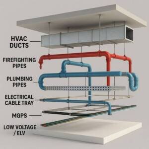
The workflow that works:
- Allocate ceiling and shaft space at concept stage, before detailed routing, so the coordination cycle starts from an agreed spatial budget.
- Model each discipline to LOD 300 with correct sizes, positions and equipment, then develop to LOD 350 for coordination — because supports, hangers and access zones are where the real conflicts live. Our guide to BIM levels of development covers what each level does and does not include.
- Federate and run structured clash detection in priority order, classified and grouped rather than as a raw dump. Our guide to BIM clash detection covers the test matrix and tolerance logic.
- Resolve in the model, in priority order, applying the hierarchy above rather than resolving by whoever objects loudest.
- Issue coordinated composites from the common data environment with status and revision applied.
- Generate documentation from the resolved model — plans, sections, schedules and penetration drawings all derived from the same coordinated source.
For the software and Revit workflow side, see our guide to MEP drafting and Revit MEP.
Seven MEP Drawing Set Failures
| Failure | What it causes | The fix |
|---|---|---|
| No composite or coordinated layout | Three correct designs that do not fit together; conflicts found on site | Composite layouts with levels and offsets as a contractual deliverable |
| Penetration drawings issued late | Coring through completed structure, or unapproved openings | Issue penetrations early enough to be cast in, coordinated against the structural package |
| Ceiling void sized before services are allocated | Lowered ceilings or lost floor-to-floor height, discovered after structural design freeze | Ceiling space allocation at conceptual routing stage |
| Coordinating by discipline convenience | Flexible services modelled first, then redone when drainage falls have nowhere to go | Route in priority order: structure, gravity drainage, main ducts, then the rest |
| Riser diagrams missing or inconsistent with plans | Undersized stacks discovered during commissioning | Riser diagrams cross-checked against floor plans at every issue |
| Sheets issued without a clear status | Installation from a review-stage drawing | Issue status in every title block, enforced at the CDE |
| Fire packages submitted last | Civil Defence comments arriving with no float remaining | Submit fire-related packages earliest, since they carry the longest review |
Frequently Asked Questions About MEP Plans in Construction
What are MEP plans in construction?
MEP plans are the construction drawings that define the design, layout, routing, sizing and specification of a building’s mechanical, electrical and plumbing systems. They are used by contractors to install, by inspectors to verify, and by the authority having jurisdiction to grant a building permit.
What does MEP stand for, and what is MEPF?
MEP stands for Mechanical, Electrical and Plumbing. MEPF or MEPFS adds Fire protection or Fire Safety — sprinklers, standpipes, detection, alarm and smoke control — which on most regional projects is reviewed by Civil Defence and carries the least routing flexibility of any discipline.
What does a complete MEP drawing set include?
Cover sheet and legend, discipline floor plans, riser diagrams, sections and elevations, details, equipment schedules, composite or coordinated layouts, penetration drawings, and as-built drawings. Sets are most often incomplete in the last three, which are precisely the ones that make an installation buildable.
What is the difference between MEP design drawings and shop drawings?
Design drawings are produced by the MEP consultant and define system performance, equipment capacities, sizes and indicative routing. Shop drawings are produced by the contractor or subcontractor and show fabrication and installation detail with actual products, supports, fixings and sequence. Between them sit composite drawings, which prove the services fit before anything is fabricated.
Which codes govern MEP drawings in Saudi Arabia?
The Saudi Building Code is the governing framework, with SBC 401 covering electrical installations, SBC 501 mechanical and HVAC, SBC 701 plumbing and drainage, and SBC 801 fire protection, which is substantially NFPA-derived. International references including ASHRAE, SMACNA, NFPA and IEC are applied alongside it as the specification directs. Confirm applicable parts and editions against the project specification, since these are updated.
Which authorities review MEP drawings in the UAE?
There is no single federal MEP code. Fire-related scope is governed by the UAE Fire and Life Safety Code of Practice and reviewed by Civil Defence. Dubai Municipality and the Abu Dhabi Department of Municipalities and Transport set emirate-level requirements including green building systems, and utilities such as DEWA publish their own electrical installation regulations. Free zones and master developers frequently add a further review layer.
What is a composite MEP Plans in Construction?
A drawing overlaying all MEP disciplines with levels and offsets shown, alongside structure, to prove the services physically fit in the space available. It is the deliverable that converts three separately correct designs into one buildable installation, and its absence is the most common gap in an otherwise complete drawing set.
Which service has priority when two systems clash?
Structure never moves. Gravity drainage comes next because its falls are fixed, then large ductwork because sections cannot be reduced without affecting airflow, then fire protection because head coverage is prescriptive, then large pressurised pipework, then cable tray and containment, and finally small-bore pipe and conduit, which are the most flexible services in the building.
Why are ceiling voids tighter on Gulf projects?
Cooling load. Buildings in Saudi Arabia and the UAE need substantially higher air volumes and chilled water flow than temperate-climate equivalents, which means physically larger ducts and pipework and more terminal units competing for the same void as containment, sprinkler mains and drainage falls. Ceiling void depth and shaft sizing therefore need to be settled at concept stage, not during coordination.
What LOD is needed for MEP coordination?
LOD 300 for correct sizes, positions and equipment, developed to LOD 350 for coordination sign-off. At LOD 300 there are no hangers, supports, brackets or access zones in the model, and those are exactly the components that cause most real conflicts. Coordination against LOD 300 produces a clean report and a plenum that cannot be installed.
What are penetration drawings and why do they matter?
Drawings showing every point where a service passes through a structural element or fire-rated barrier, with sleeve sizes, positions and firestopping details. They matter because sleeves cast into concrete are cheap and coring through completed structure is not — and because penetrations through rated barriers are reviewed by the fire authority.
Do MEP Plans in Construction need to be approved before construction?
Yes. MEP plans are permit documents reviewed by the authority having jurisdiction against the applicable codes, with fire-related scope typically reviewed separately by Civil Defence. Because authority comments arrive after consultant comments, packages that only just clear internal review have no float left when the authority responds — which is why fire packages in particular should be submitted earliest.
Conclusion
An MEP Plans in Construction set is judged by whether it can be built from, and that comes down to three things most sets get wrong: whether a composite layout proves the services fit, whether penetration drawings arrive early enough to be cast in, and whether the ceiling void was sized before the services were allocated to it rather than after.
In Saudi Arabia and the UAE there is a fourth. The codes are regional — SBC in the Kingdom, a mix of federal fire regulation and emirate-level requirements in the Emirates — and the cooling load is high enough that a plenum designed against an international reference will not hold the services the building actually needs. Coordinate for the void you have, to the code that will review you, and settle both before the structural design freezes.
Let’s get your MEP package coordinated before it reaches site.
AMC Engineer delivers HVAC and plumbing design, load and hydraulic calculations, LOD 300–500 Revit MEP modelling, Navisworks clash detection and SMACNA/ASHRAE-compliant construction documentation across Saudi Arabia and the UAE.